Nixie Clock v2
December 25, 2012
Completed six-tube IN-14 Nixie clock
For Christmas 2012, I built a Nixie clock for my girlfriend! I had previously built a four-tube Nixie clock for my parents in 2011. I decided to improve upon my previous design in various ways:
- This clock features six Nixie tubes versus four Nixie tubes, so the time can be displayed in hours:minutes:seconds format.
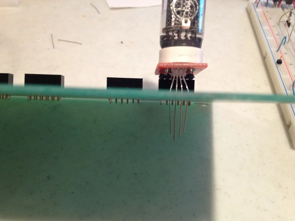
- The Nixie tubes are mounted on removable headers to easily swap out a burnt-out tube.
- The Nixie high-side "tube enable" circuitry makes use of high-voltage optoisolators. This is simpler and more robust than the dual transistor (MPSA42 & MPSA92) circuit used in the 2011 Nixie Clock.
Below are some pictures from the construction of the Nixie clock:
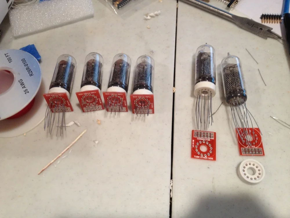
IN-14 Nixie tubes mounted on removable PCB sections
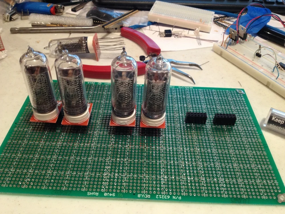
Nixie tubes mounted on a protoboard
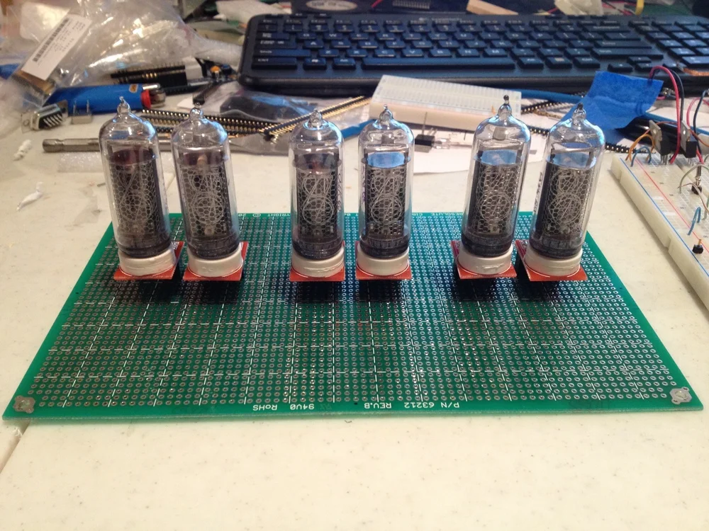
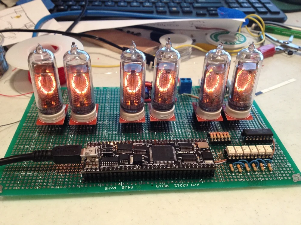
All six Nixie tubes mounted on the protoboard
RGB LED mounted beneath a Nixie tube
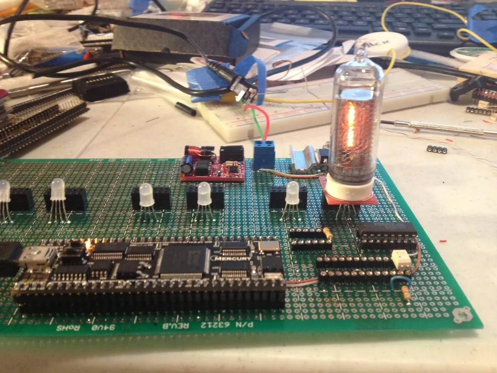
Testing with one Nixie tube.
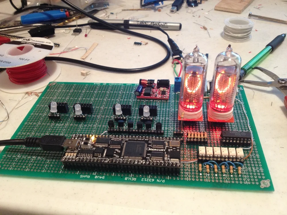
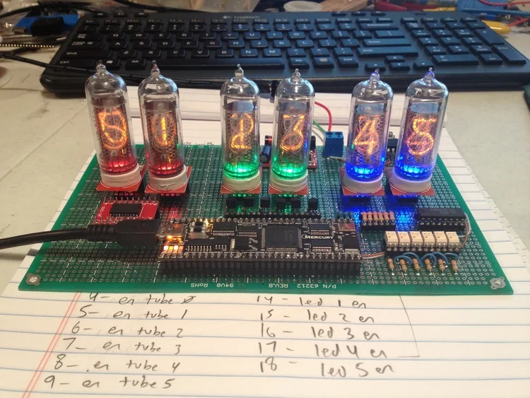
Testing with two Nixie tubes & LEDs.
The design does not contain a microprocessor! Rather, the entire clock is controlled with custom digital logic written in VHDL. This design is implemented on my Mercury FPGA module, available at MicroNova Electronics. This module packs a Spartan-3A 50K FPGA onto a 64-pin DIP package with all of the necessary support circuitry and plenty of I/O!
The Mercury board is connected to the Soviet-equivalent of the 74141 driver IC (K155NA1), which converts BCD into one-hot digit cathode driver signals. It is also connected to a bank of TLP627 optoisolators, which control the anodes for each Nixie tube. A ring counter loops through and multiplexes the tubes such that all tubes are displayed within 16.67ms (1/60Hz). About 10% "dead time" was added in-between the display of each tube to mitigate a ghosting problem that occurred, where the previous digit would be displayed on the next tube! (I think this was a result of the slow switching speed of the Soviet K155NA1.
The clock is set via a USB interface on the back of the clock that connects to the Mercury FPGA board. Time is kept with a battery-backed DS3232 real-time clock connected via I2C interface to the Mercury FPGA. The DS3232 has an internal temperature-compensated crystal oscillator (TXCO), providing accuracy of ±2ppm, or about 1 minute per year.
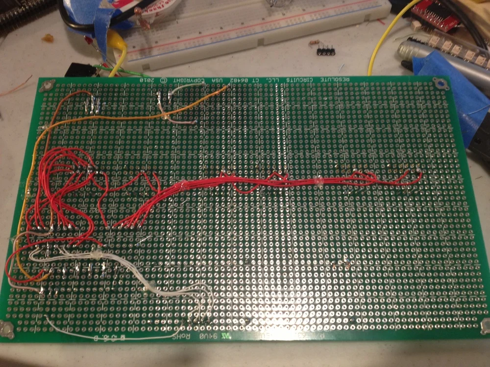
Partially-completed soldering on the underside of the protoboard.
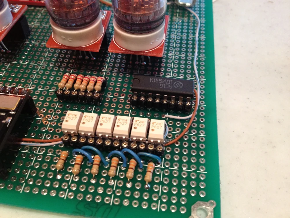
Detailed view of the TLP627 optoisolators and K155NA1 digit driver.
All six tubes wired up!
Ghosting of the previous digit! This problem was eliminated by added dead-time to the Nixie tube multiplexing circuit.
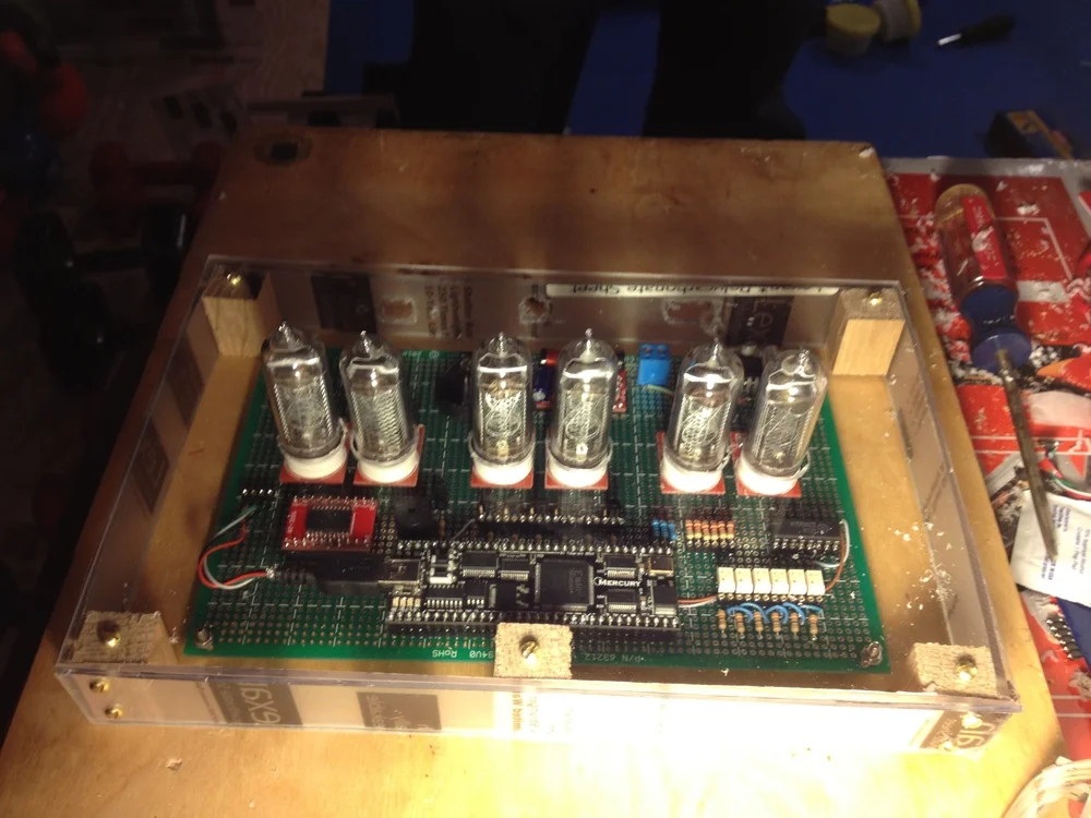
Mounting the clock in a plexiglass case.
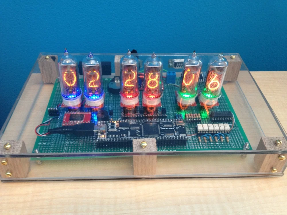
Completed Nixie clock!
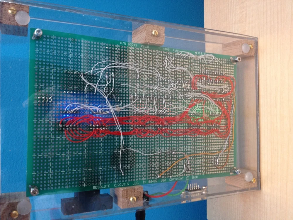
Underside of the completed Nixie clock. Next time I do this, I am definitely making a PCB! This takes way too long to solder...
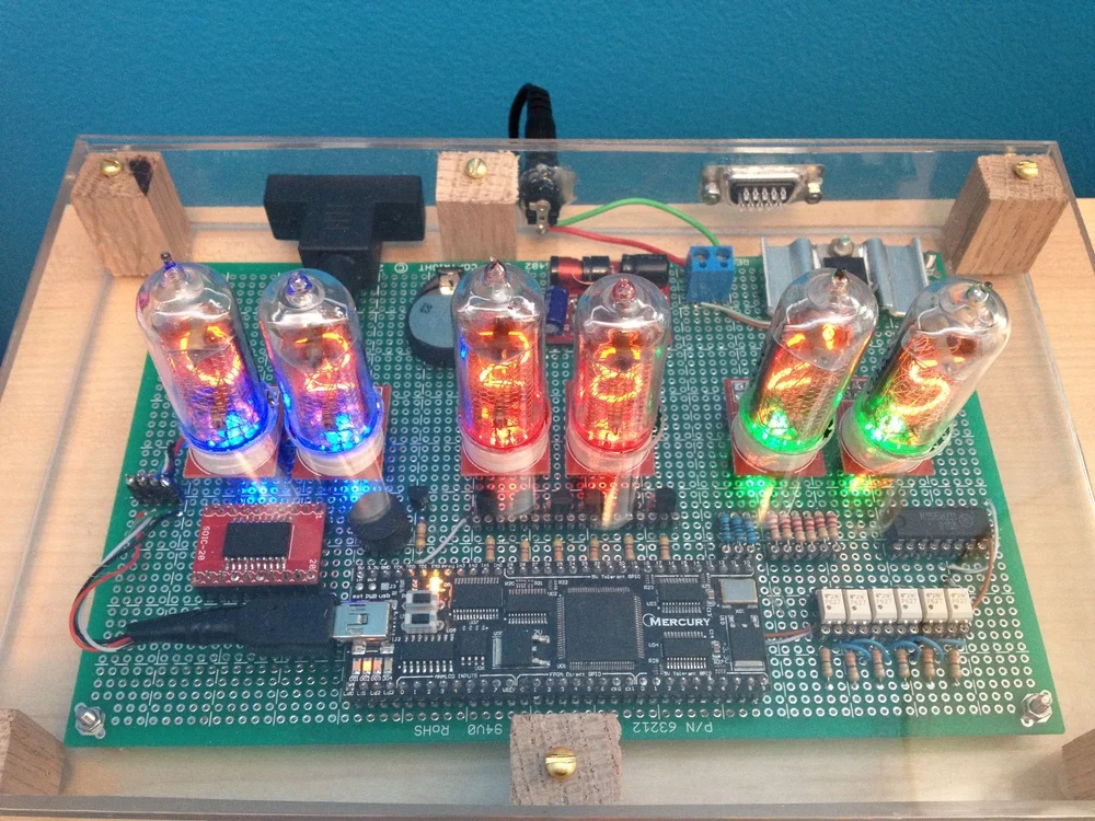
Top view of the completed Nixie clock.
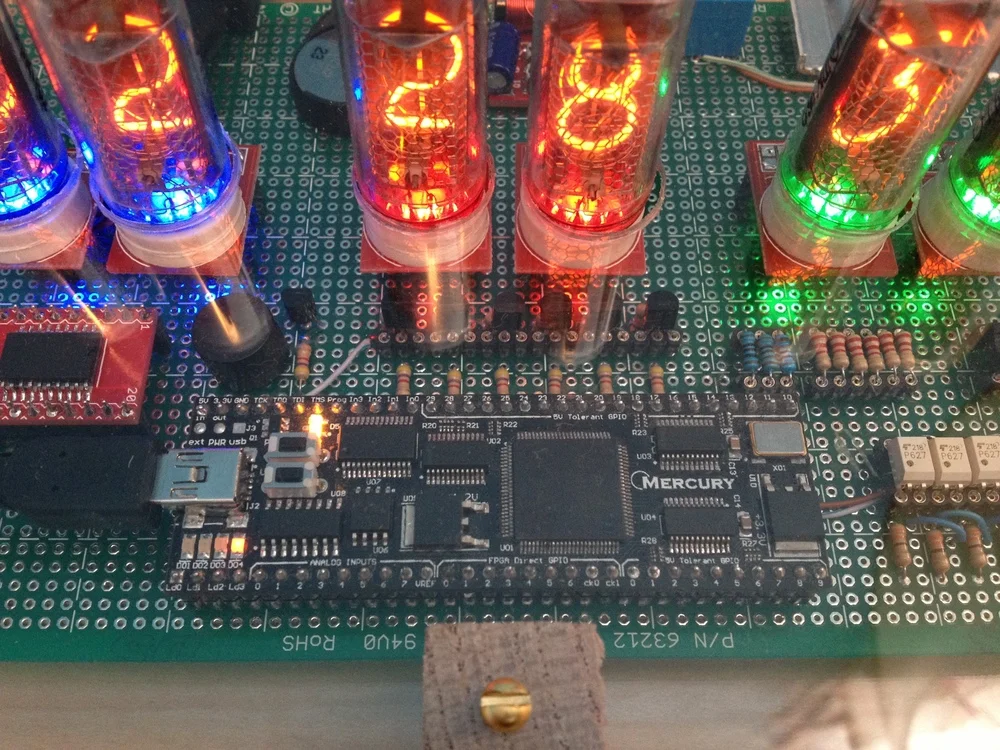
Close-up view showing the RTC, buzzer, Mercury FPGA module, LED driver transistors, and LED & tube series resistors.