Nixie Clock v1
December 25, 2011
As a gift to my parents this Christmas, I built them a Nixie Clock!
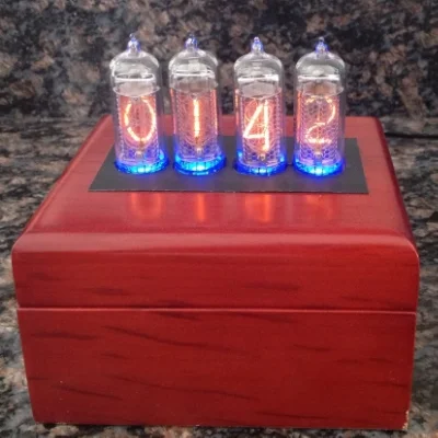
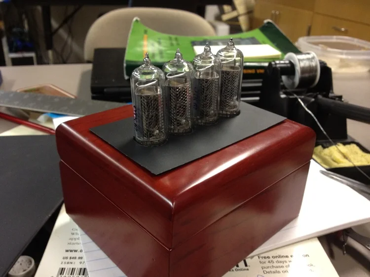
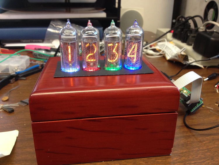
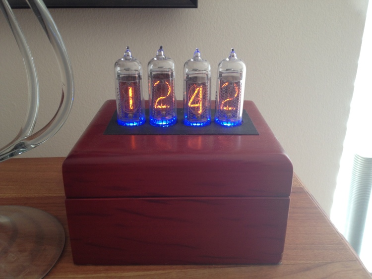
Completed Nixie Clock
I used four IN-14 Nixie tubes, imported from Ukraine. These tubes are new old stock, left over from the former Soviet Union, and were relatively inexpensive compared to their scarce western counterparts! The shape of the IN-14 was particularly appealing because it would allow the tubes to stick right out of the top of the clock!
Underneath each tube I placed an RGB LED. This provides a nice bit of color, and an additional visual indicator (for flashing the seconds, showing the user we're in 'set' mode, etc).
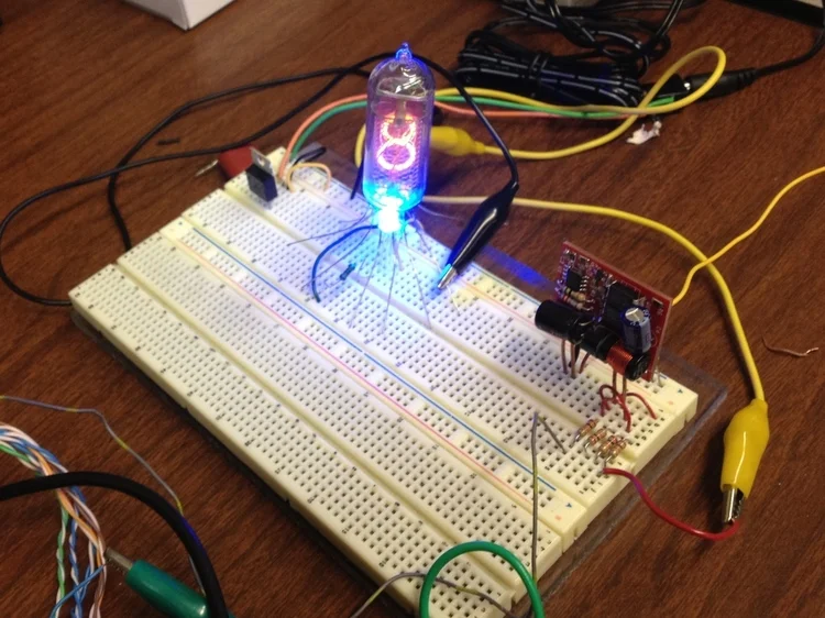
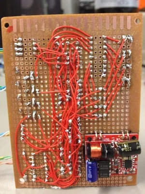
Testing a single IN-14 with an RGB LED. 180VDC tube power supply is provided by the red DC-DC converter board.
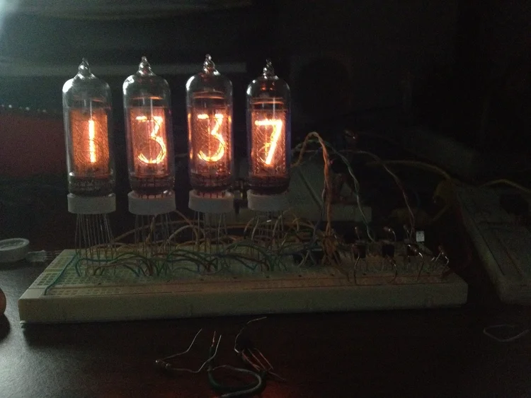
Testing all four IN-14 tubes on a breadboard!
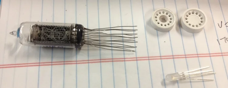
A hole was drilled in the plastic guard to allow the LEDs to be placed below each tube.

Soldering the Nixie tubes & RGB LEDs onto a perfboard.
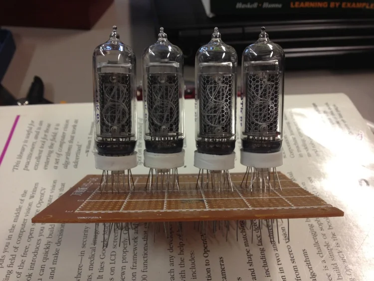
All four Nixie tubes & RGB LEDs soldered down.
Checking if everything fits.

Nixie anodes & cathodes soldered.
RGB LEDs soldered.

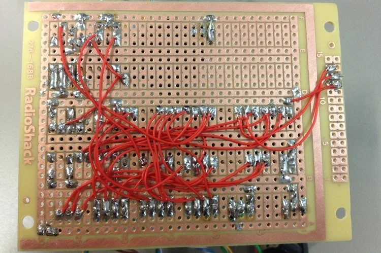
Display board: High-side HV transistors (upper left), LED transistors (upper right), low-side BCD-to-tube decoder (bottom right)
The display tubes are each enabled and disabled with a pair of high voltage transistors (MPSA42 & MPSA92) at the high-side (anode) of the tube. All the tubes share a common bus at the low-side (cathode) for each of the digits; this is connected to a 74141 IC BCD-to-decimal decoder driver. By very quickly alternating which tube is enabled, whilst simultaneously changing the digit output to the cathode driver, each tube appears to have a different digit displayed. This is a technique known as multiplexing; this greatly saves on the amount of wiring & drive circuitry needed.
The RGB LEDs are wired in a similar manner; a PNP transistor controls the high-side of each individual LED, while the color bus shared by all LEDs is wired to the output pins of the microcontroller.
Display board with pinout notes
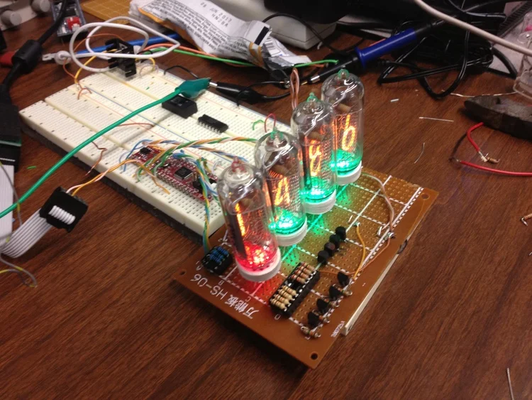
Testing display board. Microcontroller is a Wytec Dragonfly12 (HCS12 DIP module)

Microcontroller socketed & connected to display board. Testing LED colors.

Timing circuitry added to lower board.
To keep track of the current time & date, a DS1305 real-time clock was used. This connects to the HCS12 microcontroller via a SPI interface. The RTC gets its timing from a a 32.768kHz temperature-compensated crystal oscillator (DS32KHZ). This provides a clock accurate up to +/- 1 minute per year. (I opted to use one of these after my tests with ordinary 32.768kHz crystals often lost a few minutes per day!) The DS1305 RTC and the DS32KHZ TXCO are both connected to a CR2032 3V lithium battery & to the main 5V power supply. In the event that the 5V power supply is lost (due to a power outage, or moving the clock), the CR2032 keeps the real-time clock going.
Bottom of the lower board (microcontroller & timing circuitry)
Everything stuck into the case. Still running test code. Black plastic guard not yet glued down.
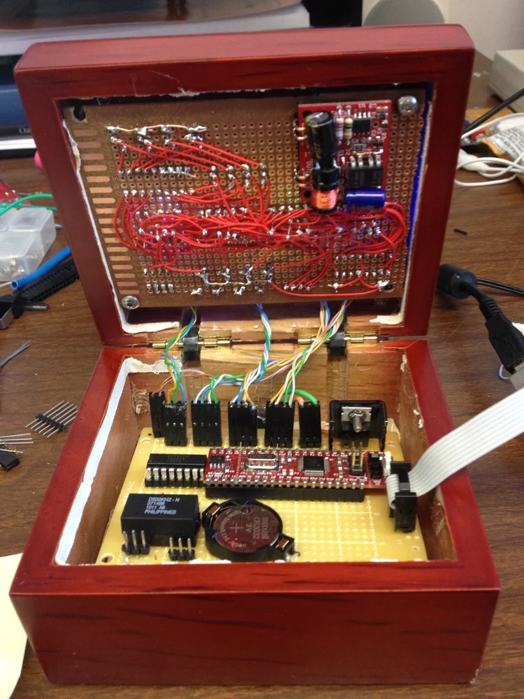
Innards of the clock.
Finished product!
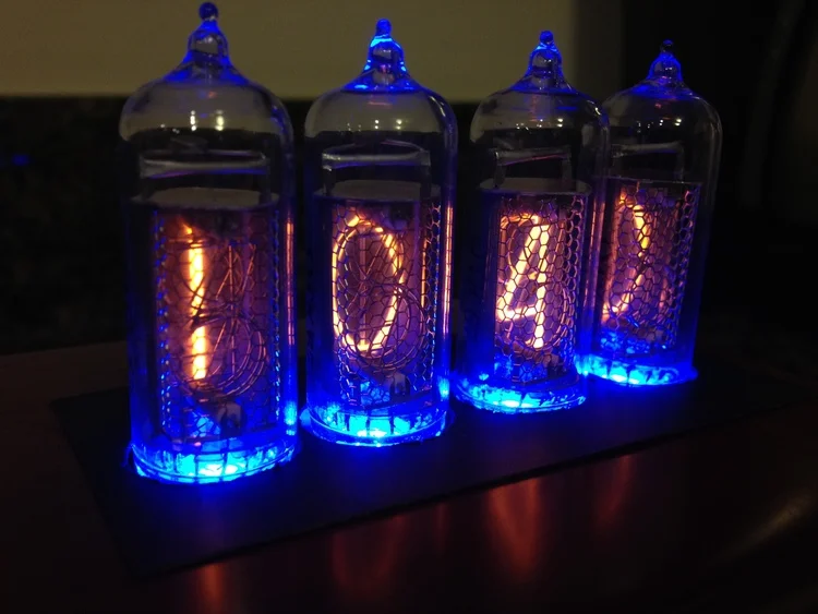
Close-up of the Nixie tubes.
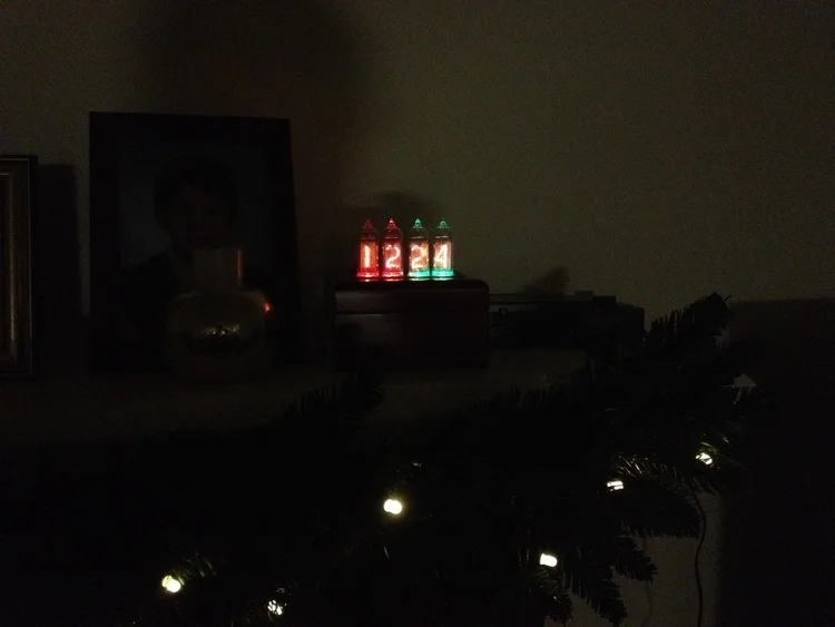
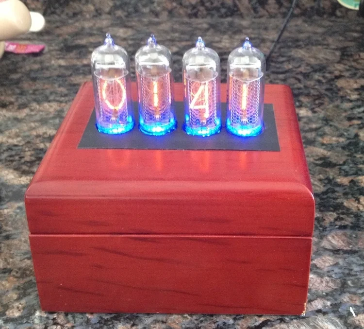
The clock can be set to alternate between the date & time. Here it is on the mantle on Christmas Eve.
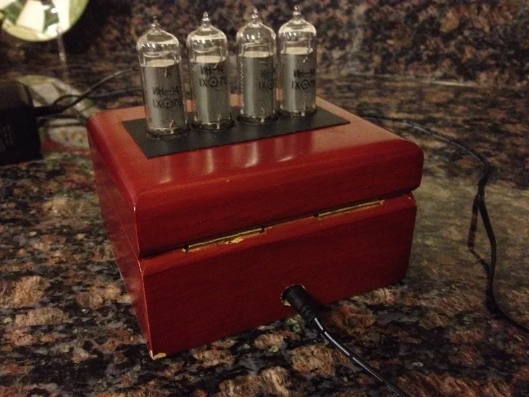
Rear end of the clock.
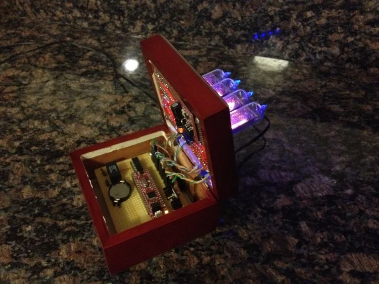
Clock opened, exposing the innards.
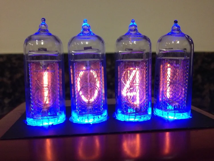
Another close up of the Nixie tubes.
Nixie clock on a sunny day.