PSoC 1 VGA Driver
By Mark Bowers and Michael Lohrer
April 16, 2012

PSoC VGA demo display
For our final project in Dr. Rawashdeh's ECE571 (Mixed-signal Embedded Systems), Michael Lohrer and I developed a VGA driver for the Cypress PSoC-1. Our implementation is capable of a 64x48 display (10-by-10 macropixels) with 3-bit (RGB) color depth, and produces an industry standard 640x480 VGA signal. Our design only requires an external oscillator, VGA connector & series resistors; no other external hardware is required. PWM blocks are used to produce very accurate VGA timing, and SPI master blocks are used to shift out the pixel data.
My HCS12 VGA driver used a single hardware counter to fire an interrupt service routine, inside of which the HSYNC, VSYNC and color signals were controlled by software. The time to service the ISR can vary by a few cycles each time, depending on which instruction it's interrupting. As a result, that implementation was a bit jittery and only worked on CRT monitors or forgiving LCD monitors. Here on the PSoC-1, we can implement much of the critical timing with digital logic blocks, which takes a load off the CPU, and results in a much more accurate signal that looked nice and crisp on every monitor we tried.

A 25.175MHz oscillator is connected to input P1[4]. This feeds a PWM16 block that produces the HSYNC signal. This produces sync pulses at the beginning of each video line. Completion of the HSYNC PWM clocks the VSYNC PWM. This produces sync pulses at the beginning of each frame. These two signals are routed out to pins. In parallel, two PWM16_DB blocks produce modified HSYNC and VSYNC signals that include the porches defined in the VGA standard, and therefore indicate the time for which a given line or frame is valid. The AND of these VIDON_H and VIDON_V signals represents the “video-on” signal for this system. This is used to gate the color signals and ensure video stability. (The color signals cannot be active outside of the active video region, or the monitor will lose a lock on the signal and fail to display an image.)
The VIDON_H and HSYNC timers need to be activated simultaneously to have the proper phase relationship! This is achieved in software by manually changing the RO0[1] LUT value from 0 to 1. This output is routed to the enable of these two timers.
A divide-by-5 counter is implemented using a COUNTER8 block. This is fed to the SPIM modules, so that they will shift out pixels at 1/10th of the pixel clock. (The SPI block shifts out at ½ of its input clock.) The output of this counter is routed to the broadcast bus. Three SPIM modules shift out the red, green and blue pixels. The output of these modules is gated by the video-on signal, to ensure that the screen is dark during the blanking period.

The external pins are configured in the following manner:
Digital Blocks Configuration
(click for larger view)
Port_0_0 = RED
Port_0_1 = GREEN
Port_0_2 = BLUE
Port_0_6 = HSYNC
Port_0_7 = VSYNC
Port_1_4 = External 25.175MHz clock
Series resistors are present on pins 0, 1, and 2, for the RED, GREEN and BLUE signals. This is because a VGA monitor has 75-ohm input impedance on the color pins.
75 / (75 + R) = 5/0.7 => solve for R = 460-ohm series resistor
The adjacent graphic illustrates the configuration of the digital blocks as seen in the PSoC creator program. This was very difficult to route manually. 15 of 16 digital blocks are consumed!
In order to route all the necessary signals, multiple global digital interconnects were required.
These interconnects allow output signals from one digital row to be routed to another input row.
It is also important to note that connections to an input row are synced to SysClk by default.
This initially caused many of the routed signals to be delayed by a clock cycle. Setting them to
asynchronous solves this issue.
The system produces a standard 640x480 signal, but due to memory bandwidth constraints, our
system operates uses 10x10 macropixels, resulting in an effective 64x48 resolution.

Display Coordinates
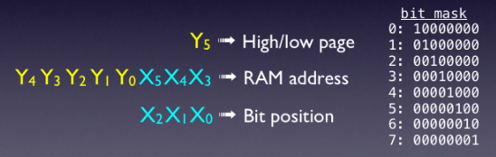
The memory on the PSoC is arranged in eight pages, each containing 256-bytes (8-bit addressing). Page 0 is used for variables, page 7 is used for the stack. The remaining 6 pages (1 through 6) are used as VRAM. Each pixel consumes a single bit of VRAM for each color. Rows contains 64-pixels (8-bytes per color). There are 48 rows of video. Pages 1, 2, and 3 contain the R/G/B information for the first 32 rows. The remaining 16 rows are stored in pages 4, 5 and 6. These pages are only ½ consumed - 128-bytes are free for other use. The X and Y coordinates are represented with 6-bits. Y[5] switches between the low pages (1 thru 3) and the upper pages (4 through 6). The concatenation of Y[4:0] & X[5:3] produces an 8-bit address with which to index in a particular memory page. This address gives us the byte where the desired pixel resides. The lower bits X[2:0] select a particular pixel within that byte. A bit mask was created in RAM to quickly map to a particular bit. Note that each time a single pixel is set, a read-modify-write is required to preserve the other 7 pixels in a byte.
Addressing Scheme
To switch among pages [3], there are several registers:
STK_PP - This sets the SRAM page for stack instructions (PUSH and POP).
MVR_PP - This sets the SRAM page for the MVI instruction when reading
MVW_PP - This sets the SRAM page for the MVI instruction when writing
IDX_PP - This sets the SRAM page for indexed memory instructions.
CUR_PP - This sets the SRAM page for all other instructions.
The upper bits [7:6] of the F register set the paging mode:
Page mode 00: Current page is 0, Indexed page is 0
Page mode 01: Current page is 0, Indexed page is STK_PP
Page mode 10: Current page is CUR_PP, Indexed page is IDX_PP
Page mode 11: Current page is CUR_PP, Indexed page is STK_PP
Page mode 11 is the default operation of the C compiler. This allows switching between pages
for immediate accesses, and indexed memory instructions can access specific stack elements.
When an interrupt fires, the F register is pushed to the stack and the page mode is set to 00.
There are also four registers, TMP_DRx, that are NOT used by the C compiler and have no
predefined function. The intent of these registers is to provide an extra location to juggle data
while paging. The pixel-writing routines make use of these registers.

VGA timing (red arrows indicate ISR firing)
Two interrupts are configured for video:
1. Fires with the VSYNC pulse - This resets various software counters used by the main video ISR:
- VGA_vback (counts 35 lines for the SP and BP)
- VGA_repeats (repeats each line 10 times)
- VGA_row (counts the VGA row from 0 to 47)
- VGA_ptr (indexes into memory 0-255)
- VGA_active (flag to determine if we are in porches or actively displaying)
2. Fires at the conclusion of VIDON_H - This keeps the SPIM blocks fed for a line of video.
Below is a simplified diagram of the video interrupt service routine. The ISR fires at the end of VIDON_H assertion. When the interrupt fires, a counter determines whether or not the line is in the active video region. If the line is in an active video region, the ISR prepares to feed the SPI blocks. The A, X and IDX_PP registers are preserved. X is loaded with the pointer into the VRAM, and the page mode is set to 10. This enables the IDX_PP register for indexed assembly instructions. This is followed by 8 macro calls that feed the SPI shift-out registers for R, G and B. The repeat counter ensures that lines are repeated 10 times. The active video region is exited after 48 lines.
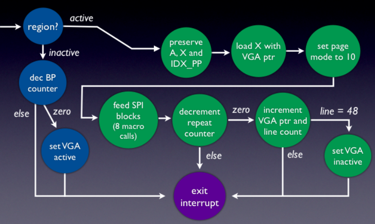
Simplified horizontal ISR diagram
In order to control what is displayed, the VRAM must be edited. This involves writing to the correct page, and setting the appropriate bits to set the desired color. In order to facilitate this, a small API has been created. Assembly was used in the lowest level functions, such as clearing the screen and writing a pixel, to provide the best possible speed.
The primary function is pixel_set(). This is written in assembly and takes the vertical and horizontal coordinates as arguments, as well as three bits determining what color is to be set. The vertical coordinate can be in the range of 0-47, and the horizontal coordinate can be in the range of 0-63. The pixel color is set by the lowest three bits of the last byte passed to the function. These bits correspond to the red, green, and blue in the pixel being set to on or off.
This function has to first calculate the address of the pixel to set, based on the input arguments. The arguments are all passed on the stack, because they will not fit into the available registers. In the below code sample, X is set to the stack pointer’s value, and the contents of the stack are shown in the comments:

During this project, it was discovered that the M8C core provides several temporary data registers, that are unused by the C compiler. These proved to be quite useful for assembly routines, to facilitate data transfers. In the pixel_set() function, a temporary data register is used to store the color data, so that indexed instructions can be used later to access a separate page from the stack.

This function could be optimized, however, if the programmer wanted to set 8 bits at a time. This would no longer require bitwise logic, but a simple MOV instruction for each color. Therefore, a block_set() function was written in assembly to take advantage of this. This function has the desired block, vertical coordinate, red byte, green byte, and a blue byte of data as input. The block is a value from 0-7, since there are eight 8-bit blocks making up the 64 pixel row. The vertical coordinate is the same as in the pixel_set() function, and the three bytes of color data and mapped directly to the colors that will be set for the eight pixels. So, if the programmer desired to display all yellow pixels in block 3, row 20, the function would be called as follows: block_set(3,20,0xFF,0xFF,0x00).
The last routine written in assembly is clear_screen(). This function has no arguments, but simply moves 0x00 into every VRAM location. As a reference, this function was calculated to take 874µs, which means it can be completed before the screen is refreshed.

PSoC-1 resource usage. A good chunk of RAM is left over, but the CPU is almost always busy feeding the color shift registers!
To test functionality of the pixel_set() function, a C function write_char() was created. This function requires a horizontal and vertical coordinate for the top left corner of the character to be written, a pointer to the letter array, a color to set the letter, and a background color to set every other pixel. The character arrays are formatted as an eight high by seven wide array of bits, with a 1 representing a part of the character, and 0 being the background.
Functions created to utilize the block_set() function are the write_line() and set_screen() functions. The write_line() function has the desired row and colors as input, and sets the whole row of pixels to the desired color. The set_screen() function is an extension of this function, and sets a rectangle of the screen as the specified color. It requires and x1,y1 coordinate for the top left; x2,y2 for the bottom right corner, and the color.

Mandelbrot set rendered & displayed on the PSoC-1